English
 Русский
 العربية
Variable Frequency Adjustable Speed Marine Use Three Phase Induction Motor
- Introduction
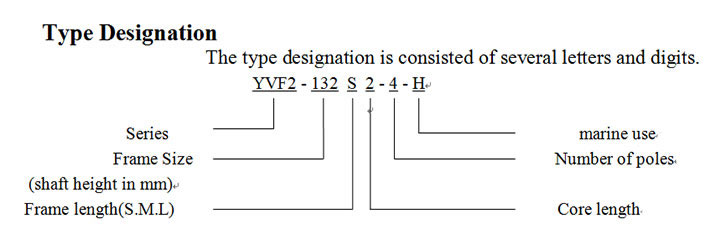
- Type Designation
- Operating Conditions
- Main Technical Data
- Ordering Information

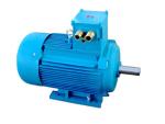
The YVF2-H series of variable frequency adjustable speed three-phase induction motor is an energy-efficient AC adjustable speed motor. Equipped with a frequency converter, the induction motor features low noise and vibration, a high starting torque, small starting current, and reliable operation. Flat and step less speed regulation can be done in 3(5)~100Hz or more and an independent forced cooling fan makes the motor long lasting. The motor drives various machines on ships such as pumps, blowers, separators, hydraulic engines and other auxiliary equipment.
This series is designed according to IEC60034-1《Rotating Electrical Machines—Rating And Performance》and "Rules for the Construction of Sea-Going Steel Ships." Motors also comply with the following specifications.
IEC60034 Rotating electrical machines
IEC60068 Environmental testing
IEC60072 Dimensions and power ratings for rotating electrical machines
IEC60092 Marine electric accessories
The motors also meet international standards for the following Ship Classification Societies:
LR Lloyd’s Register of Shipping
GL Germanischer Lloyd
NK Nippon Kaiji Kyokai
BV Bureau Veritas
KR Korea Register of shipping
RINA Registro Italiano Navale
ABS American Bureau of Shipping
The type and size of bearings used in these motors are given in table 1. Table 1
| Frame Size | No. of Poles | Bearings | ||
| Driving End | Non-Driving End | |||
| B3, B5, B35 | V1 | |||
| 80 | 4, 6 | 6204-2R S /C3 | 6204-2RS/C3 | |
| 90 | 4, 6 | 6205-2RS/C3 | 6205-2RS/C3 | |
| 100 | 4, 6 | 6206-2RZ/C3 | 6206-2RZ/C3 | |
| 112 | 4, 6, 8 | 6206-2RZ/C3 | 6206-2RZ/C3 | |
| 132 | 4, 6, 8 | 6208-2RZ/C3 | 6208-2RZ/C3 | |
| 160 | 4, 6, 8 | 6309-2RZ/C3 | 6309-2RZ / C3 | |
| 180 | 4, 6, 8 | 6311 / C3 | 6311 / C3 | |
| 200 | 4, 6, 8 | 6312 / C3 | 6312 / C3 | |
| 225 | 4, 6, 8 | 6313 / C3 | 631 2 / C3 | |
| 250 | 4, 6, 8 | 6314 / C3 | 631 3 / C3 | |
| 280 | 4, 6, 8 | 631 7/ C3 | 631 4 / C3 | |
| 315 | 4, 6, 8 | 631 9/ Z2 | 7319ACJ | 6319/Z2 |
| 355 | 4, 6, 8 | 6322 / Z2 | 7322ACJ | 6322/Z2 |
Operating Conditions
Ambient temperature: 0℃~45℃
Altitude: 0m
Relative humidity: ≤95%
Frozen dew: Exist
Salt mist: Exist
Oil mist: Exist
Fungus: Exist
Shock: Exist
Vibration: Exist
Inclination and Swing: ±22.5°
Voltage and Frequency
Rated voltage: 380V
Rated frequency: 50Hz
Range of Frequency
The frame of motors from 80 to 225 with a permanent torque range of 5~50Hz have a power range frequency of 50~100Hz. The frame of motors from 250 to 355 with a permanent torque range of 3~50Hz have a power range frequency of 50~100Hz.
Duty Type
Continuous(S1)
Insulation, Temperature Rise
Insulation F
Temperature rise of winding (resistance method): 100K
Allowable working temperature of bearing: 90℃
Driving Method
Pulley, spur of flexible coupling can be used for driving.
Noise
When using the frequency converter as the power supply, the noise limits (A sound power level) of the motors measured at the no-load conditions are given in Table 2.
Vibration
When using the frequency converter as the power supply, the effective values of vibration intensity bound measured at no-load conditions do not exceed those given in table 3.
Mounting arrangements
Mounting arrangements are available for various frame sizes shown in Table 4. We can also provide customized mounting arrangements.
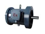
B3 Horizontal, foot-mounted
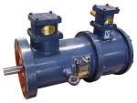
B5 Horizontal flange-mounted
B35 Horizontal, foot and flange mounted
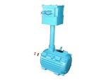
V1 Vertical, flange mount
| Power kW | Synchronous Speed r/min | ||
| 1500 | 1000 | 750 | |
| Sound Power Level dB(A) | |||
| 0.55 | 79 | 79 | 79 |
| 0.75 | |||
| 1.1 | |||
| 1.5 | 83 | 83 | 83 |
| 2.2 | |||
| 3 | 87 | 87 | 87 |
| 4 | |||
| 5.5 | 91 | 91 | 91 |
| 7.5 | |||
| 11 | 93 | 93 | 93 |
| 15 | |||
| 18.5 | |||
| 22 | 98 | 98 | 98 |
| 30 | 101 | 101 | 101 |
| 37 | |||
| 45 | 103 | 103 | 103 |
| 55 | |||
| 75 | 105 | 105 | 105 |
| 90 | |||
| 110 | 107 | 107 | 107 |
| 132 | |||
| 160 | 109 | 109 | 109 |
| 200 | |||
| 250 | 111 | - | - |
| 315 | |||
| 355 | 113 | 113 | 113 |
| Frame size | ≤ 132 | > 132 ~ 225 | > 225 ~ 500 |
| Vibration intensity bound mm/s | 1.8 | 2.8 | 3.5 |
| Frame size | Mounting Arrangements ( IM ) |
| 80 ~ 280 | B3, B5, B35, V1 |
| 315 ~ 355 | B3, B35, V1 |
Impregnation and Surface Treatment
The surfaces of the motors’ winding and metal spares are impregnated and well treated to be waterproof and resistant to fungus, mold and sea spray in accordance with specifications for machines in humid environments.
Technical Data
Technical data for motors are given in tables 5-7. Upon request, we can produce 2-pole motors.
Note: All data is for reference only and may change depending upon specifications of your order. Contact us with any questions.
| Frame size | Rated power(kW) | Rated Current (A) | Rated torque (N· m ) | Max torque/ Rated torque | Permanent torque range of frequency (Hz) | Permanent power range of frequency (Hz) |
| YVF2-80M1-4-H | 0.55 | 1.5 | 3.5 | 2.3 | 5 ~ 50 | 50 ~ 100 |
| YVF2-80M2-4-H | 0.75 | 2.1 | 4.7 | |||
| YVF2-90S-4-H | 1.1 | 2.7 | 7.0 | |||
| YVF2-90L-4-H | 1.5 | 3.6 | 9.5 | |||
| YVF2-100L 1 -4-H | 2.2 | 5.0 | 14.0 | |||
| YVF2-100L 2 -4-H | 3 | 6.8 | 19.0 | |||
| YVF2-112M-4-H | 4 | 8.9 | 25.4 | |||
| YVF2-132S-4-H | 5.5 | 11.7 | 35.0 | |||
| YVF2-132M-4-H | 7.5 | 15.4 | 47.7 | |||
| YVF2-160M-4-H | 11 | 22.6 | 70.0 | |||
| YVF2-160L-4-H | 15 | 30.5 | 95.5 | |||
| YVF2-180M-4-H | 18.5 | 35.9 | 117.1 | |||
| YVF2-180L-4-H | 22 | 42.2 | 140.9 | |||
| YVF2-200L-4-H | 30 | 57.3 | 190.9 | |||
| YVF2-225S-4-H | 37 | 70.2 | 235.5 | |||
| YVF2-225M-4-H | 45 | 84.0 | 286.4 | |||
| YVF2-250M-4-H | 55 | 104 | 350.1 | 3 ~ 50 | ||
| YVF2-280S-4-H | 75 | 139 | 477.7 | |||
| YVF2-280M-4-H | 90 | 164 | 572.9 | |||
| YVF2-315S-4-H | 110 | 201 | 700.2 | 2.2 | ||
| YVF2-315M-4-H | 132 | 240 | 840.3 | |||
| YVF2-315L 1 -4-H | 160 | 289 | 1018 | |||
| YVF2-315L 2 -4-H | 200 | 361 | 1273 | |||
| YVF2-355M-4-H | 250 | 464 | 1592 | |||
| YVF2-355L-4-H | 315 | 582 | 2005 |
| Frame size | R ated power (kW) | Rated Current (A) | Rated torque (N· m ) | Max torque/ Rated torque | Permanent torque range of frequency (Hz) | Permanent power range of frequency (Hz) |
| YVF2-90S-6-H | 0.75 | 2.2 | 7.2 | 2.1 | 5 ~ 50 | 50 ~ 100 |
| YVF2-90L-6-H | 1.1 | 3.2 | 10.5 | |||
| YVF2-100L-6-H | 1.5 | 4.0 | 14.3 | |||
| YVF2-112M-6-H | 2.2 | 5.8 | 21 .0 | |||
| YVF2-132S-6-H | 3 | 7.2 | 28.7 | |||
| YVF2-132M 1 -6-H | 4 | 9.5 | 38.2 | |||
| YVF2-132M 2 -6-H | 5.5 | 12.5 | 52.5 | |||
| YVF2-160M-6-H | 7.5 | 17.1 | 71.6 | |||
| YVF2-160L-6-H | 11 | 25.0 | 105 .1 | |||
| YVF2-180L-6-H | 15 | 33.0 | 143 .2 | |||
| YVF2-200L 1 -6-H | 18.5 | 37.6 | 17 6. 7 | |||
| YVF2-200L 2 -6-H | 22 | 44.7 | 210 .1 | |||
| YVF2-225M-6-H | 30 | 61.1 | 286.5 | |||
| YVF2-250M-6-H | 37 | 71.0 | 353.4 | 3 ~ 50 | ||
| YVF2-280S-6-H | 45 | 86.4 | 429.8 | 2.0 | ||
| YVF2-280M-6-H | 55 | 103 | 525.3 | |||
| YVF2-315S-6-H | 75 | 141 | 716.3 | 2.0 | 3 ~ 50 | 50 ~ 100 |
| YVF2-315M-6-H | 90 | 169 | 859.5 | |||
| YVF2-315L 1 -6-H | 110 | 205 | 105 1 | |||
| YVF2-315L 2 -6-H | 132 | 246 | 126 1 | |||
| YVF2-355M 1 -6-H | 160 | 302 | 1528 | |||
| YVF2-355M 2 -6-H | 200 | 377 | 1910 | |||
| YVF2-355L-6-H | 250 | 469 | 238 8 |
| Frame size | R ated power (kW) | Rated Current (A) | Rated torque (N· m ) | Max torque/ Rated torque | Permanent torque range of frequency (Hz) | Permanent power range of frequency (Hz) |
| YVF2-132S-8-H | 2.2 | 5.8 | 2 8. 0 | 2.0 | 5 ~ 50 | 50 ~ 100 |
| YVF2-132M-8-H | 3 | 7.6 | 38.2 | |||
| YVF2-160M 1 -8-H | 4 | 10.5 | 50.9 | |||
| YVF2-160M 2 -8-H | 5.5 | 13.4 | 70.0 | |||
| YVF2-160L-8-H | 7.5 | 17.7 | 95. 5 | |||
| YVF2-180L-8-H | 11 | 25.6 | 1 40. 1 | |||
| YVF2-200L-8-H | 15 | 33.3 | 191.0 | |||
| YVF2-225S-8-H | 18.5 | 40.3 | 235.6 | |||
| YVF2-225M-8-H | 22 | 47.4 | 278.1 | |||
| YVF2-250M-8-H | 30 | 64.7 | 382.0 | 3 ~ 50 | ||
| YVF2-280S-8-H | 37 | 79.8 | 471.1 | |||
| YVF2-280M-8-H | 45 | 94.8 | 573.0 | |||
| YVF2-315S-8-H | 55 | 114 | 700.3 | |||
| YVF2-315M-8-H | 75 | 152 | 955 .0 | |||
| YVF2-315L 1 -8-H | 90 | 179 | 114 6 | |||
| YVF2-315L 2 -8-H | 110 | 218 | 1 400 | |||
| YVF2-355M 1 -8-H | 132 | 265 | 16 81 | |||
| YVF2-355M 2 -8-H | 160 | 320 | 203 7 | |||
| YVF2-355L-8-H | 200 | 399 | 254 7 |
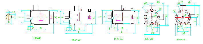
Mounting and Overall Dimensions
Various mounting types and overall dimensions are shown respectively in Table.8 to 11.
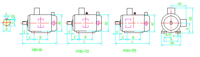
| Frame Size | Mounting Dimensions | Overall Dimensions | ||||||||||||
| A | B | C | D | E | F | G a | H | K b | AB | AC | AD | HD | L | |
| Basic Dimension | Basic Dimension | Basic Dimension | Basic Dimension | Basic Dimension | Basic Dimension | Basic Dimension | Basic Dimension | Basic Dimension | ||||||
| 80M | 125 | 100 | 50 | 19 | 40 | 6 | 15.5 | 80 | 10 | 165 | 165 | 145 | 220 | 3 7 0 |
| 90S | 140 | 56 | 24 | 50 | 8 | 20 | 90 | 180 | 195 | 1 55 | 250 | 400 | ||
| 90L | 125 | 430 | ||||||||||||
| 100L | 160 | 140 | 63 | 28 | 60 | 24 | 100 | 12 | 205 | 215 | 18 0 | 270 | 465 | |
| 112M | 190 | 70 | 10 | 112 | 230 | 240 | 190 | 300 | 4 9 0 | |||||
| 132S | 216 | 89 | 38 | 80 | 33 | 132 | 270 | 275 | 21 0 | 345 | 5 30 | |||
| 132M | 178 | 57 5 | ||||||||||||
| 160M | 254 | 210 | 108 | 42 | 110 | 12 | 37 | 160 | 15 | 320 | 330 | 255 | 420 | 6 60 |
| 160L | 254 | 715 | ||||||||||||
| 180M | 279 | 241 | 121 | 48 | 14 | 42.5 | 180 | 355 | 380 | 2 8 0 | 45 5 | 810 | ||
| 180L | 279 | 850 | ||||||||||||
| 200L | 318 | 305 | 133 | 55 | 16 | 49 | 200 | 19 | 395 | 420 | 305 | 505 | 890 | |
| 225S | 356 | 286 | 149 | 60 | 140 | 18 | 53 | 225 | 435 | 470 | 3 35 | 560 | 930 | |
| 225M | 311 | 18 | 970 | |||||||||||
| 250M | 406 | 349 | 168 | 65 | 58 | 250 | 24 | 490 | 5 1 0 | 370 | 615 | 1050 | ||
| 280S | 457 | 368 | 190 | 75 | 20 | 67.5 | 280 | 550 | 5 80 | 410 | 680 | 1 100 | ||
| 280M | 419 | 20 | 71 | 11 80 | ||||||||||
| 315S | 508 | 406 | 216 | 80 | 170 | 22 | 71 | 315 | 28 | 635 | 645 | 5 30 | 845 | 1330 |
| 315M | 457 | 1390 | ||||||||||||
| 315L | 508 | 1480 | ||||||||||||
| 3 55M | 610 | 560 | 254 | 95 | 170 | 25 | 86 | 355 | 730 | 730 | 655 | 1100 | 1750 | |
| 3 5 5 L | 630 | 1800 |
||||||||||||
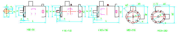
| Frame Size | Mounting Dimensions | Overall Dimensions | ||||||||||||
| D | E | F | G a | M | N | P b | S D | T | Number of Holes on the Flange | AC | AD | HF | L | |
| Basic Dimension | Basic Dimension | Basic Dimension | Basic Dimension | Basic Dimension | Basic Dimension | Basic Dimension | ||||||||
| 80M | 19 | 40 | 6 | 15.5 | 165 | 130 | 200 | 12 | 3.5 | 4 | 175 | 145 | 185 | 3 7 0 |
| 90S | 24 | 50 | 8 | 20 | 195 | 155 | 195 | 400 | ||||||
| 90L | 430 | |||||||||||||
| 100L | 28 | 60 | 24 | 215 | 180 | 250 | 15 | 4.0 | 215 | 180 | 245 | 465 | ||
| 112M | 240 | 190 | 265 | 490 | ||||||||||
| 132S | 38 | 80 | 10 | 33 | 265 | 230 | 300 | 275 | 210 | 315 | 5 30 | |||
| 132M | 575 | |||||||||||||
| 160M | 42 | 110 | 12 | 37 | 300 | 250 | 350 | 19 | 5.0 | 330 | 255 | 385 | 6 60 | |
| 160L | 715 | |||||||||||||
| 180M | 48 | 14 | 42.5 | 380 | 280 | 430 | 810 | |||||||
| 180L | 850 | |||||||||||||
| 200L | 55 | 16 | 49 | 350 | 300 | 400 | 420 | 305 | 480 | 890 | ||||
| 225S | 60 | 140 | 18 | 53 | 400 | 350 | 450 | 8 | 470 | 335 | 535 | 930 | ||
| 225M | 970 | |||||||||||||
| 250M | 65 | 58 | 500 | 450 | 550 | 510 | 370 | 595 | 1060 | |||||
| 280S | 75 | 20 | 67.5 | 580 | 410 | 650 | 1100 | |||||||
| 280M | 1180 | |||||||||||||
| Frame Size | Mounting Dimensions | Overall Dimensions | ||||||||||||||||||
| A | B | C | D | E | F | G A | H | K D | M | N | P B | S D | T | Number of Holes on the Flange | AB | AC | AD | HD | L | |
| Basic Dimension | Basic Dimension | Basic Dimension | Basic Dimension | Basic Dimension | Basic Dimension | Basic Dimension | Basic Dimension | Basic Dimension | Basic Dimension | Basic Dimension | Basic Dimension | |||||||||
| 80M | 125 | 100 | 50 | 19 | 40 | 6 | 15 . 5 | 80 | 10 | 165 | 130 | 200 | 12 | 3.5 | 4 | 165 | 175 | 145 | 2 20 | 3 7 0 |
| 90S | 140 | 56 | 24 | 50 | 8 | 20 | 90 | 180 | 195 | 155 | 250 | 400 | ||||||||
| 90L | 125 | 430 | ||||||||||||||||||
| 100L | 160 | 140 | 63 | 28 | 60 | 24 | 100 | 12 | 215 | 180 | 250 | 15 | 4.0 | 205 | 215 | 180 | 270 | 465 | ||
| 112M | 190 | 70 | 112 | 230 | 240 | 190 | 300 | 4 9 0 | ||||||||||||
| 132S | 216 | 89 | 38 | 80 | 10 | 33 | 132 | 265 | 230 | 300 | 270 | 275 | 210 | 345 | 5 30 | |||||
| 132M | 178 | 57 5 | ||||||||||||||||||
| 160M | 254 | 210 | 108 | 42 | 110 | 12 | 37 | 160 | 15 | 300 | 250 | 350 | 19 | 5.0 | 330 | 330 | 255 | 420 | 6 60 | |
| 160L | 254 | 715 | ||||||||||||||||||
| 180M | 279 | 241 | 121 | 48 | 14 | 42 .5 | 180 | 355 | 380 | 280 | 45 5 | 810 | ||||||||
| 180L | 279 | 850 | ||||||||||||||||||
| 200L | 318 | 305 | 133 | 55 | 16 | 49 | 200 | 19 | 350 | 300 | 400 | 395 | 420 | 305 | 505 | 8 90 | ||||
| 225S | 356 | 286 | 149 | 60 | 140 | 18 | 53 | 225 | 400 | 350 | 450 | 8 | 435 | 470 | 335 | 560 | 930 | |||
| 225M | 311 | 970 | ||||||||||||||||||
| 250M | 406 | 349 | 168 | 6 5 | 58 | 250 | 24 | 500 | 450 | 550 | 490 | 510 | 370 | 61 5 | 1050 | |||||
| 280S | 457 | 368 | 190 | 75 | 20 | 67.5 | 280 | 550 | 580 | 410 | 680 | 110 0 | ||||||||
| 280M | 419 | 11 80 | ||||||||||||||||||
| 315S | 508 | 406 | 216 | 80 | 170 | 22 | 71 | 3 1 5 | 28 | 600 | 550 | 660 | 24 | 6.0 | 6 35 | 6 45 | 5 3 0 | 845 | 1330 | |
| 315M | 457 | 1390 | ||||||||||||||||||
| 3 15L | 508 | 1480 | ||||||||||||||||||
| 3 5 5 M | 610 | 560 | 254 | 95 | 25 | 86 | 355 | 28 | 740 | 680 | 800 | 24 | 6.0 | 8 | 7 3 0 | 710 | 655 | 1100 | 1750 | |
| 355L | 630 | 1800 |
||||||||||||||||||
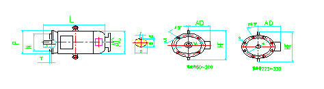
| Frame Size | Mounting Dimensions | Overall Dimensions | ||||||||||||
| D | E | F | G a | M | N | P | S d | T | Number of Holes on the Flange | AC | AD | HF | L | |
| Basic Dimension | Basic Dimension | Basic Dimension | Basic Dimension | Basic Dimension | Basic Dimension | Basic Dimension | ||||||||
| 80 | 19 | 40 | 6 | 15.5 | 165 | 130 | 200 | 12 | 3.5 | 4 | 165 | 175 | 260 | 370 |
| 90S | 24 | 50 | 8 | 20 | 180 | 180 | 270 | 400 | ||||||
| 90L | 430 | |||||||||||||
| 100L | 28 | 60 | 24 | 215 | 180 | 250 | 15 | 4.0 | 205 | 195 | 300 | 465 | ||
| 112M | 230 | 205 | 320 | 490 | ||||||||||
| 132S | 38 | 80 | 10 | 33 | 265 | 230 | 300 | 270 | 265 | 380 | 530 | |||
| 132M | 575 | |||||||||||||
| 160M | 38 | 110 | 12 | 37 | 300 | 250 | 350 | 19 | 5.0 | 325 | 270 | 450 | 660 | |
| 160L | 715 | |||||||||||||
| 180M | 48 | 14 | 42.5 | 380 | 280 | 500 | 788 | |||||||
| 180L | 820 | |||||||||||||
| 200L | 55 | 16 | 49 | 350 | 300 | 400 | 420 | 305 | 550 | 960 | ||||
| 225S | 60 | 140 | 18 | 53 | 400 | 350 | 450 | 8 | 470 | 335 | 610 | 1020 | ||
| 225M | 1060 | |||||||||||||
| 250M | 65 | 58 | 500 | 450 | 550 | 510 | 370 | 650 | 1160 | |||||
| 280S | 75 | 20 | 67.5 | 580 | 410 | 720 | 1220 | |||||||
| 280M | 1300 | |||||||||||||
| 315S | 80 | 170 | 22 | 71 | 600 | 550 | 660 | 24 | 6.0 | 645 | 530 | 900 | 1530 | |
| 315M | 1520 | |||||||||||||
| 315L | 1610 | |||||||||||||
| 355M | 95 | 170 | 25 | 86 | 740 | 680 | 800 | 710 | 655 | 1100 | 1890 | |||
| 355L | 1940 |
|||||||||||||
Ordering Information
1. When placing an order, specify the motor’s type, output, number of poles, voltage, frequency, mounting arrangement and any other requirements.
2. Customized features include the double shaft extension, position of the terminal box, coding device and brake, and thermistor protection.
3. We also offer 2P frequency changeable motors upon request.